3.3. System volume and frost protection
Domestic heat pump systems need enough liquid volume and proper flow rates to ensure they have enough heat for defrosting and to prevent ice build-up.
System volume
Domestic heat pump systems must carry out a defrost cycle at times to prevent ice build-up on the external heat exchanger (evaporator). This is carried out using the thermal energy in the heat transfer medium. It’s important to make sure that enough thermal energy will be available when required. This is achieved by making sure the total volume of liquid permanently available in the distribution circuit is sufficient to hold enough energy when operating at the expected minimum flow temperature.
Heat pump manufacturers provide data on the required heating circuit volume under certain circumstances as seen in the table below:
| Air source heat pump | 3.5kW | 5kW | 7kW | 10kW | 12kW |
|---|---|---|---|---|---|
| Flow rate, minimum (litres per minute) | 6.66 | 9 | 16.58 | ||
| Flow rate, maximum (litres per minute) | 14.3 | 20.08 | 34.41 | ||
| Minimum water volume in the heating circuit (litres) | 15 / 40 | 20 / 55 | 45 / 150 | ||
Source: Vaillant “Be ready for the energy change”
Here we can see two figures for minimum system volume. The larger figure is with a minimum flow temperature of 15°C and the smaller volume, a minimum flow temperature of 25°C. The minimum flow temperature determines the volume, not the design flow temperature which will be considerably higher.
The volume of liquid in the pipework alone will typically not be enough to meet this requirement. Some householders may opt for multiple towel rails or bathroom radiators without thermostatic radiator valves (TRVs), in which case the liquid in these can be added to the volume, but some systems may require the addition of a volumiser or buffer tank to meet the required volume.
See MCS best practice guide section 11.1 for more information.
Flow rate and glycol
The power of a heating circuit, or the rate of heat transfer, is dependent on the flow rate and the temperature difference between flow and return. It can be calculated using the Power / Flow Rate / Delta T equation:
Q = m x SHC x Δt
Where:
Q = power (kW)
m = mass flow (l/s)
SHC = specific heat capacity of the water/glycol mix
Δt = the temperature difference (drop) between flow and return
From this we can see that, if the ‘Δt’ is reduced or the SHC altered by the addition of glycol, the mass flow ‘m’ must be increased to maintain the same heat output.
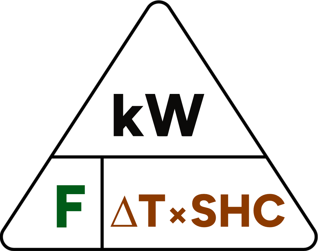
This is sometimes represented as a triangle showing:
- Power in kW represents the calculated power output of the heat generator (Q).
- Flow rate in litres per second. Most manufacturers use litres per minute (l/m) or per hour (l/hr), but some use cubic metres per hour (m3/hr). Calculators are readily available online.
- Temperature differential between flow and return is known as delta-T, Δt or simply the delta. This is multiplied by the specific heat capacity of the medium in the primary circuit. In the two examples below we will use water (4.184) and glycol mixed to 25% -10°C protection (3.835)
Example:
| Air source heat pump | 3.5kW | 5kW | 7kW | 10kW | 12kW |
|---|---|---|---|---|---|
| Flow rate, minimum (litres per minute) | 6.66 | 9 | 16.58 | ||
| Flow rate, maximum (litres per minute) | 14.3 | 20.08 | 34.41 | ||
| Minimum water volume in the heating circuit (litres) | 15 / 40 | 20 / 55 | 45 / 150 | ||
Source: Vaillant “Be ready for the energy change”
Using the manufacturer’s data table from before, we can see that the 7kW heat pump needs a maximum flow of 20.08 l/m. The heat pump works to a target delta of 5°C.
Water has a specific heat capacity of 4.184 J/gK so, if we use water as our heat transfer medium, the equation looks like this:
20.08 l/m ÷ 60 = 0.335 l/s
5 x 4.184 = 20.92
0.335 x 20.92 = 7.01 kW
However, if we add glycol at 25% mix, to give us frost protection to -10°C, the equation would look like this:
20.08 ÷ 60 = 0.335 l/s
5 x 3.835 = 19.175
0.335 x 19.175 = 6.42 kW
While glycol provides robust frost protection it also reduces the unit’s power output under the same operating conditions.
Using the equation in the flow rate triangle can provide valuable information whilst on site. For example, for an existing heat pump where the flow rate is known (ie from interrogation of the heat pump controller or measurement via a visual indicator and sensors), along with the difference between flow and return temperatures (Δt) and the specific heat capacity of the heat medium (determined from the concentration of glycol) a snapshot of the heat pump’s power output can be produced. The glycol concentration can be measured via a refractometer and the result referenced on the table below.
Alternatively, you may have a system where you know the maximum power output of the heat pump (from the data badge) and want to know if the indicated flow rate (from interrogation of the heat pump controller or via a visual indicator) is sufficient to allow for the heat pump to deliver its full rated power output or if it’s contributing to poor performance for example.
Using the table below we can experiment with different glycol concentrations and see how changing only the specific heat capacity as displayed in the third column affects the maximum power output of a heat generator, in this case the heat pump.
| Glycol percentage % | Freeze temperature ℃ | Specific heat capacity |
|---|---|---|
| 0 | 0 | 4.184 Clean Water Index |
| 5 | -1.7 | 4.114 |
| 10 | -3.3 | 4.044 |
| 15 | -5 | 3.975 |
| 20 | -7.2 | 3.905 |
| 25 | -10 | 3.835 |
| 30 | -13.3 | 3.765 |
| 35 | -17.2 | 3.696 |
Source: Daikin monobloc stage 1 training materials – Ian Judd
Alternative approaches to frost protection
Frost protection for monobloc heat pumps is essential to avoid serious damage to the condenser in the event of a power cut or fault with the unit in freezing conditions. The condenser or plate heat exchanger within the outdoor unit is a specialist piece of engineering. Replacing the condenser on a new unit can potentially cost as much as a replacement outdoor unit, once the labour for the different trades involved, materials and refrigerant have been included.
Whilst glycol is a proven frost protection solution, it does impact our ability to transfer the maximum effective power output of the unit. The alternative is to install a pair of anti-freeze valves and use water as the heat transfer medium, protected with corrosion inhibitor chemicals and biocide to protect against bacteria growth.
Anti-freeze valves are becoming much more common, and manufacturers are now in support of their use. It’s important to ensure this last line of defence against frost damage is installed having met any additional requirements as detailed in the manufacturer’s instructions, data sheets, or installer reference guides.
Characteristic components
Operating principle
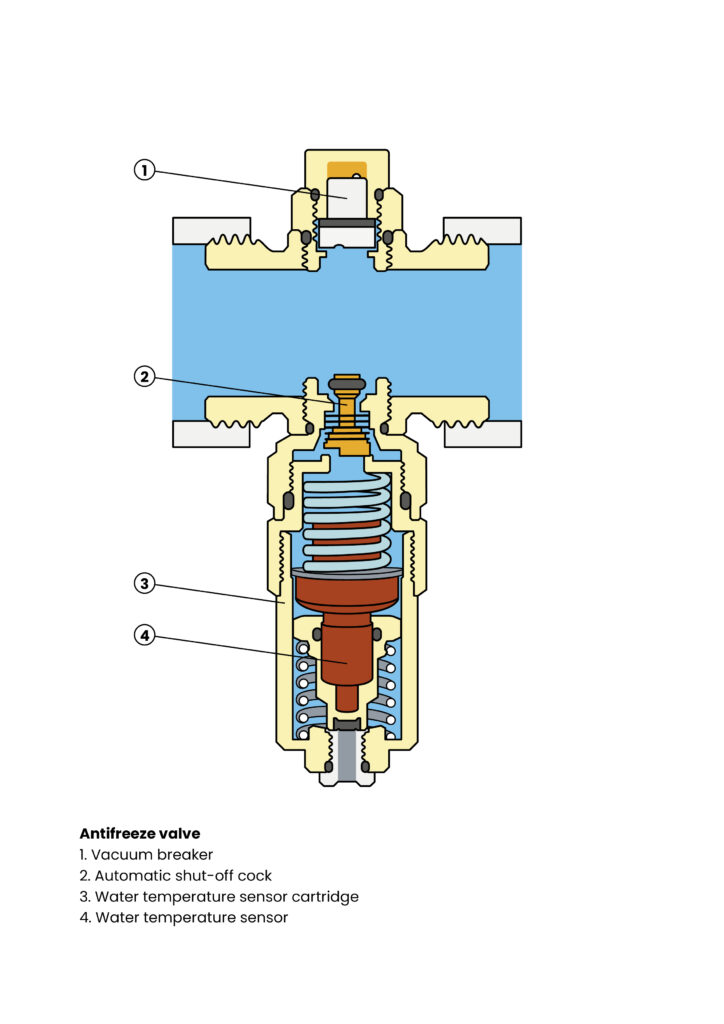
Antifreeze valve
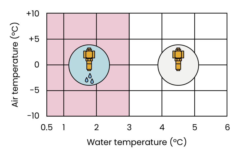
The Caleffi 108 series antifreeze valve as shown in the table below begins drainage of the primary circuit when the medium within the circuit’s temperature reaches a value of 3ºC.
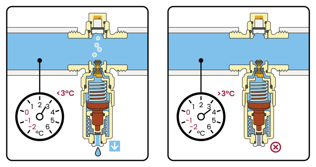
The device must only be installed in a vertical position, with the outlet facing downwards and free from obstructions, to allow the drained water to flow out properly. The antifreeze valves must be installed outdoors, where the lowest temperatures can be reached, and well away from sources of heat. Valves should preferably be fitted on both pipes (flow and return).
Care should be taken when insulating pipework where anti-freeze valves are installed. Manufacturer’s instructions should be consulted at this stage.
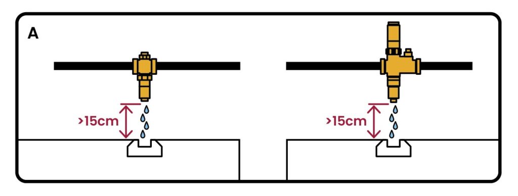
Leave at least 15cm clearance from the ground (figure A) to prevent ice which may form from below stopping water from draining from the valve.
Route the drain to a suitable collection point.
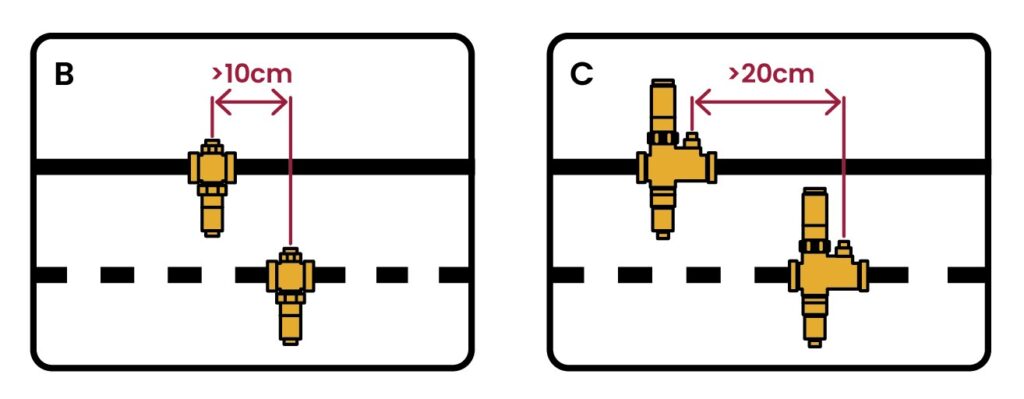
Keep a distance of at least 10cm between the antifreeze valves (figure B) and 20cm between the antifreeze valves incorporating an air sensor (figure C).