3.5. How to make microbore pipes work
It’s commonly believed that heat pumps can’t work with distribution systems that include any mini or microbore pipe, however, this is not always the case.
It’s commonly believed that heat pumps can’t work with distribution systems that include any mini or microbore pipe, however, this is not always the case. Heat pumps operate at lower temperatures than most boilers, so if the same heat output is to be provided then we need a higher flow rate. If some, or all, the pipework is narrower than standard, then we will need higher velocity of flow to deliver this, which may cause problems. The flow velocity should stay within the range of 0.5 – 1.5 m/s and best practice is a velocity of around 0.9 – 1.0 m/s.
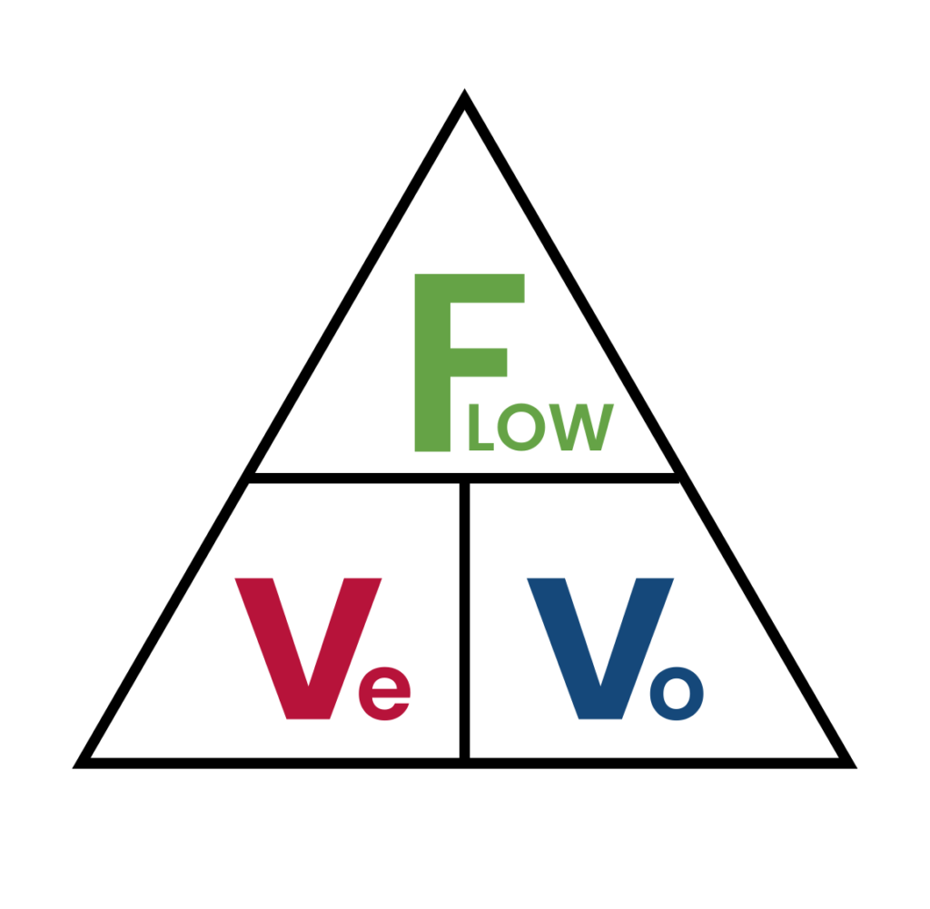
Using the flow triangle equation (see section 3.3 System volume and frost protection) we can calculate the flow rate needed for any emitter. From here we can use reference tables or calculations to ensure we can remain within the acceptable velocity range.
For example:
| Room | Heat loss (Watts per m2) | Calculated heat loss (W) | Radiator oversize factor | Expected SPF | Design temp °C | Flow temp @ DOT | Watts needed at calculated MWDT | New rad size | Watts output (W) |
|---|---|---|---|---|---|---|---|---|---|
| Utility room | 81.06 | 421.92 | 3.1 | 4.13 | 18 | 45 | 1307.94 | 700x900 P+ | 1379 |
Source: Peter Emmerson, The Renewable Technology Collective
The utility room in this property requires the new emitter to emit 1308 watts of heat at the Design Outdoor Temperature (DOT). The final metre of pipework currently installed reduces to 10mm and it would require removal of a number of fitted units to upgrade it to 15mm. We are running a 5°C delta and using water as our heat transfer medium.
It’s important to understand if this is possible with the existing pipework and what impact would this have compared to upgrading the final metre to 15mm copper.
Using the flow triangle equation (see section 3.3 System volume and frost protection), we can take the watts needed for the radiator at the design temperature (1308W) and divide it by our delta T x SHC of water (20.92). We need 0.0625 litres per second at the design flow temperature.
To check our velocity is within an acceptable range we can use another equation:

We know our flow rate is 0.062 litres per second and the volume of a metre of 10mm pipework is 0.06 litres. As such 0.0625 dived by 0.06 = 1.04 m/s which is within our acceptable range and this section of pipe, whilst increasing the pressure, will manage to move the heat energy required to heat the radiator at the design temperature.
In reality you would ensure the pipework could supply enough heat energy to meet the radiator’s stated power output, and calculate the pressure required to maintain this flow rate through any pipework of reduced bore size.
For comparison, here is the same equation again but with the last metre as 15mm pipe. Our flow rate is still 0.062 litres per second, but we have a volume of 0.146 litres per metre. As before 0.062 divided by 0.146 = 0.42 m/s
In this example, the velocity of the water in the microbore pipe is acceptable, and the increase in pressure will be limited due to the short length of narrow pipe. Longer pipe runs on smaller bore pipework will have significant impacts on pressure drop as well as flow rate, and so the longer the microbore pipe run, the higher the likelihood that you’ll need to replace it.
| Table W Microbore | Table X 6mm - 159mm | Table Y 6mm - 108mm | |||
|---|---|---|---|---|---|
| O/D mm | Capacity kg/m | O/D mm | Capacity kg/m | O/D mm | Capacity kg/m |
| 6 | 0.0169 | 6 | 0.0169 | 6 | 0.0139 |
| 8 | 0.0347 | 8 | 0.0347 | 8 | 0.0302 |
| 10 | 0.0558 | 10 | 0.0615 | 10 | 0.0529 |
| 12 | 0.089 | 12 | 0.0818 | ||
| 15 | 0.1416 | 15 | 0.128 | ||
| 18 | 0.2063 | 18 | 0.1952 | ||
| 22 | 0.314 | 22 | 0.2943 | ||
| 28 | 0.5308 | 28 | 0.505 | ||
| 35 | 0.822 | 35 | 0.7888 | ||
| 42 | 1.2163 | 42 | 1.1758 | ||
| 54 | 2.0712 | 54 | 1.9317 | ||
| 67 | 3.2134 | 67 | 3.2375 | ||
| 76 | 4.1699 | 76 | 4.0438 | ||
| 108 | 8.6107 | 108 | 8.2527 | ||
| 133 | 13.2647 | ||||
| 159 | 18.8351 | ||||
Source: Lawton Tubes