3.1. Heat loss calculations – detailed guidance
The process of calculating heat loss can seem quite daunting at first, particularly for a heating engineer who has never carried one out before. Every house presents unique challenges, but as you do more calculations, your confidence will grow, and you will develop a system that helps you work through the process effectively and quickly.
An accurate room-by-room heat loss calculation is fundamental to ensuring a heat pump can provide adequate heating throughout a property, while at a relatively low flow temperature and at high efficiency. This section outlines the steps to conduct an in-depth room-by-room heat loss calculation. You’ll be equipped with the knowledge to calculate an accurate heat loss estimate that will provide a solid foundation for the design and specification of the heat pump system.
The benefits of an accurate heat loss calculation include:
- Accurately sized emitters allowing all rooms to achieve the specified comfort level at the design outside temperature (DOT), and throughout the rest of the year as weather compensation adjusts the flow temperature.
- Enhanced customer satisfaction and positive feedback, with fewer complaints about underheated rooms, reinforcing your reputation as a reliable installer.
- Less risk of high operating costs from an undersized heat pump working overtime, or from an oversized unit with excessive cycling.
- Controlled installation costs through correct sizing of the heat pump, and avoidance of any unnecessary pipework upgrades.
- Increased heat pump lifespan and reduced maintenance costs.
Room-by-room calculations carried out by heating engineers have their limitations. A heat loss calculation to BS EN12831-1:2017 has constraints and challenges. Use this guide to minimise uncertainty.
The main challenge with heat loss calculations is not the methodology but the number of variables, particularly given the time constraints at this stage in the quotation process. Factors such as in-situ U-values, thermal bridging, and airtightness can vary considerably and have a significant impact. The process can be made more difficult by undocumented material characteristics, diverse construction techniques, the quality of building work, natural and unnatural degradation and alterations that may not be recorded.
To reduce uncertainty and increase accuracy, it’s recommended, when possible, to combine the room-by-room heat loss calculation with the building’s heat transfer coefficient (HTC). The HTC is a measure of the rate of heat loss per degree temperature difference between inside and out and tells how well the home keeps heat in and cold out. More information on the relationship between HTC and space heating demand can be found in this detailed guide.
If the property is a new build or significant renovation project, it may be possible to complete the room-by-room heat loss calculation and subsequent specification from architectural drawings. The owner or architect will be able to provide you with scaled plans and U-values of the building fabric.
If it’s an existing property and the heat pump is to be retrofitted, then a detailed site survey will be needed.
Several apps are now available to help with heat loss calculations. These simplify the process and reduce the risk of human error.
Preparation
Before your site visit, check if the property has an Energy Performance Certificate (EPC) using the Scottish EPC register. An existing EPC will give you insights including:
- total square meterage
- current type of heating system
- central heating and domestic hot water estimated annual usage.
Though some assumptions will have been made for the EPC, there will be useful information including the fabric used in the construction and the level of insulation. This can be helpful during your site visit, later during the desk-based review, and when creating the performance estimate. If the house has recently been sold, the schedule or home report may include a floorplan. If you need to make your own floor plan, then you could opt for a heat loss calculation app that offers this, or 3D modelling with lidar from your phone or tablet.
If the owner has already received support from Home Energy Scotland, they will have a Home Energy Report which will also provide some useful information for a basic design and provide an initial cost prior to completing a full survey and quotation.
Equipment essentials for the site visit:
- A laser measure can make the process easier. Ensure it has sufficient charge and is clean, so you don’t mark any surfaces.
- A tape measure is great for checking radiator sizes and areas where the laser may not be suitable.
- A notepad and a worksheet are useful unless using an appropriate app that can gather any customer information you have before your site visit.
Building fabric
Measuring the heat that escapes from a building through its walls, floors, roof and windows is a key part of the heat loss calculation to size a heat pump. Below are some recommendations to measure the fabric heat loss:
- Use the information from the EPC (if available) as a reference, record internal, party and external wall construction methods making your best assessment of the materials used. Refer to the Domestic heating design guide (2021) | CIBSE section (3.8.1) or the MCS heat load calculator for help with specific U-values or common construction methodology values.
- Speak to the owner/occupier who may have information that can help, especially with any insulation that may have been fitted since an EPC assessment was carried out. They may also have information on any renovations or alterations.
- Make note of which rooms have a room above and the room type, and which have a roof or loft space above. This is important as unheated adjoining spaces can influence the amount of heat loss from a room.
- Take note of the thickness of insulation in the loft, the type of roof construction and materials used.
- Take note of which rooms are on the ground floor and whether the floor is solid or suspended. If hatches are accessible these may allow you to verify the presence of any insulation.
- Record the dimensions of access points including gates, doors and the usable loft hatch. If any heat pump equipment is to be sited there, whilst not technically part of the heat loss calculation, recording this information will save you time and effort later.
- Note the condition of windows, their frame material, glass construction and age. Roof windows are treated differently – see Domestic heating design guide (2021) | CIBSE (section 3.5.2.5) for more guidance.
- Heat is lost when warm air leaves the house. This heat may be lost through open doors, windows and ventilation, but will also be lost through gaps and cracks in the building structure. This is known as ‘ventilation’ heat loss. The incoming cold air must be warmed to replace that heat. Draughts, ventilation (passive and mechanical), windows, doors, hatches and open fireplaces all have an impact on the air change range of a building and of each room.
U-values top tips:
- Slates are given the same U-value as tiles.
- Some doors and windows will have published U-values from the manufacturer.
- Underfloor insulation can cause issues as homeowners often don’t know if it has been installed. The EPC assumption will be that there is no insulation unless it has been visually verified.
- A worst-case scenario is best employed in these situations as advised by the CIBSE Domestic Heating Design Guide (section 3-16).
- A stove or log burner with doors does not count as an open fire with throat restriction.
- If you are unsure if the given value is correct for the wall construction, you can add the components in Domestic heating design guide (2021) | CIBSE table 3.12 together to create a custom U-value.
Existing heating system
Though technically not part of the calculation, it’s important to consider the following whilst on site, as the heat loss calculation site visit forms part of the overall design and specification of an effective and efficient heating system:
- Pipe sizes: Consider if the sizes of existing pipes are suitable to move the heat energy required to heat the space, given the increased flow rates and the need to keep the water velocity within acceptable levels (for more information see Domestic heating design guide (2021) | CIBSE section 5.6.3.3).
- Pipe routes: It’s important to identify how the primary pipework will enter the building and join into any existing system.
- Existing radiator types and sizes: Ensure you make a note of the space available should you need to fit or relocate a larger radiator. Identify if some of the existing radiators can be used in other spaces or if their output can be augmented with additional radiators in the same space.
- Position, type and size of the hot water tank: Consider the effectiveness and suitability of the mains cold water supply, and D2 discharge pipework sizing and effectiveness if installed.
Room data review
Before you leave the property, you should have collected the following data. Use the relevant sections from the Domestic heating design guide (2021) | CIBSE where appropriate:
- Internal design temperature – sections 3-16 and table 3.6.
- Air changes – table 3.8.
- The presence of any fireplaces that are open or with throat restriction. Closed fireplaces or wood burning/multifuel stoves that only operate with the doors closed should not be included. See sections 3-22.
- Is the property in an exposed location? See sections 3-19.
- Does the room have a room above it or the roof/loft?
- Is there a room below, and if so which room, or is it the ground floor?
- A note of the emitter type and size.
- The overall floor area (adding together the sections if you have split the space to make the measurements easier).
- Room height – for halls with stairwells one method that may be useful is to treat the ground floor hall as one room and then the upstairs as another. This avoids the factor for high ceilings and confusion around the stairwell space being heated by ground or first floor heat emitters.
Other room considerations
- Some software allows you to easily calculate the vaulted ceiling dimensions. If there are multiple bedrooms, it’s worth making notes of their positions in the floorplan or save pictures for easy reference. When talking to the customer explain your numbering system if you are using one or show them a plan. They are unlikely to number rooms in the same way you do.
- Accurate measurements of the different wall types are also important. Party walls and main wall construction need to be considered, as well as any areas where the homeowner has had additional insulation added. Your software system and/or manual calculator should allow for this, and the different wall types and their U-values can then be added and calculated.
- Referring to the EPC may be helpful, if one is available, or a Home Energy Report from Home Energy Scotland.
- If your software supports it, you can differentiate between multiple types of windows, as well as account for roof glazing and doors.
- Consideration of adjacent unheated spaces including conservatories and unheated porch/lobby areas is important. This will affect the heat load given, as any wall to an unheated space will be treated as if the temperature in that space is 10 degrees. See sections 3-19.
Photos
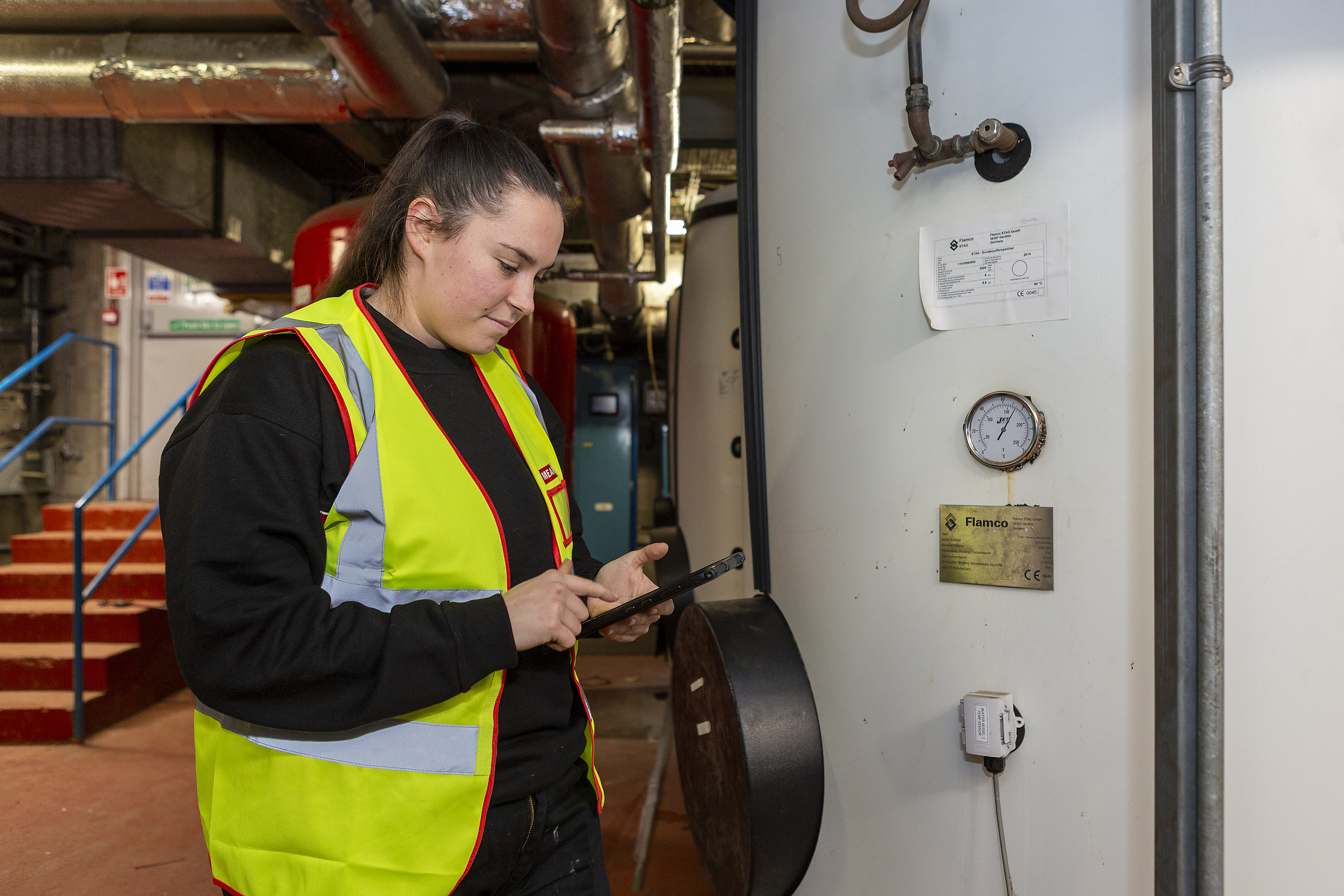
Taking photos when visiting a site will be helpful for the review, specification and pre installation stages. With the homeowner/occupier’s permission take as many photos as possible of the following:
- external wall material
- insulation in loft and underfloor
- windows and doors
- existing boiler
- cylinder cupboard
- electric supply – fuse board and main incoming fuse space for additional consumer unit, if required
- existing heating system – radiators, underfloor heating manifold, controls
- potential outdoor unit location.
Location for the external unit
A noise assessment will be needed for the proposed outdoor unit location. It’s good to do this at an early stage to ensure the system is designed around a suitable location. It’s important to identify any requirement for planning permissions depending on location and or noise levels. Information on noise limits is detailed in MCS 020 as is a template for noise assessment calculation. For more information on planning permission please visit the 2.3 Planning permission sub-chapter in this toolkit.
After your site visit
Following the site visit, it’s important to thoroughly review the data to ensure there have been no errors. The information you have collected will need to be brought together and the room heat losses calculated. You can either use the worksheet and tables in the CIBSE design guide, MCS heat load calculator or other manual calculators, or use an electronic system that is MCS approved.
There are multiple available, so try some to identify which system is right for you. There are constant updates to these systems. Recently added features include lidar scanning of rooms and floor plan layouts which can then help with schematics and radiator placement, and reduce the workload needed to prepare your installation team.
Some software-based systems will calculate detailed temperature and weather data from the address. You can check it against the data compiled by BizEE. Some software will automatically calculate the DOT or external design temperature. If you need to find the altitude of a site, you can use maps coordinates or Google Earth.